I have built and run two Manned Experimental Propagation Transmitters on 10.140073Mhz to enable myself and others to observe the propagation conditions on that band.
I decided from the outset that I would use a PIC microprocessor to generate my call sign for identification purposes. Thus positive identification should be guaranteed.
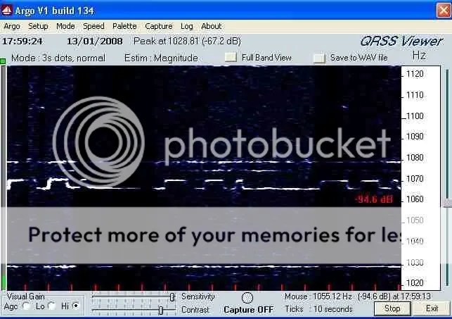
My first MEPT used QRSS3, three seconds per dot Morse code. Soon it was recommended by stations in Australia to use QRSS10 for greater readability with lower signal strengths.
I thus used QRSS10 for a long period.
When looking for my own signal on the WWW network of Grabbers I sometimes had much difficulty with positive identification. I have even looked at a Morse ident and managed to fit my call letters to it only to realise after a time that it was a Capture from 40 meters and my signal is on 30 meters.
This can arise due to fading which causes parts of the Morse code to be lost. All stations running QRSS10 will be producing dots spaces and dashes of uniform length, many combinations of received elements can fit an expected pattern if some parts are lost.
Compare this with the simple Ramp, Sawtooth or Squiggle used by some stations. Providing the characteristics of the Squiggle are unique the signal can be identified with much less information.
“It is the correct Frequency there is a Squiggle therefore it must be ‘X’.”
Squiggles are used because they are a simple KISS approach to identification. I was thinking about building a new even lower power MEPT and considering KISS identification. Could I generate square waves with a 3 to 1 Mark Space Ratio and gate just 2.333 of them out as a ‘G’ in Morse.
After some experimentation I settled on an LM555 oscillator with a 27 second cycle and equal Mark Space Ratio for character timing. This signal Triggers and Gates another LM555 which generates a 3 Second Mark 1 Second Space square wave train. The use of Mylar timing capacitors ensures stable timing which has not wandered during long 24/7 test periods.
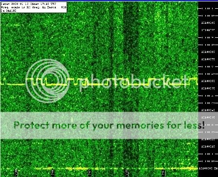
I added a long rise and fall time to the FSK modulation to give unique shape to the waveform. Another identification feature arose due to the first ‘Mark’ after ‘Trigger’ being slightly longer than the next, a feature I eagerly retained.
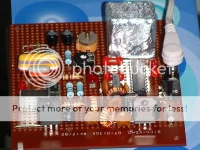
‘G’ MEPT uses two chips 74HC240 and LM556 to produce 25mW of Morse identified Beacon

OK there are 3 chips, I had no LM556’s in the Junk Box.
I have again used the concept of the ‘Crystal Cool Box’ as opposed to a Crystal Oven. An oven could be consuming more power than the complete transmitter. The Crystal is hermetically sealed in a Polyurethane Foam Cube.

Long term temperature stability is very good using this method. The ‘Cool Box’ has come of age in this light weight version, the Cube being lined with adhesive Aluminium Foil. The outer box in previous versions was made from copper clad PCB.
The initial on air test produced a report from Belgium.

Quickly followed by New Zealand.
 Italy
Italy
 Nova Scotia

Netherlands
 France